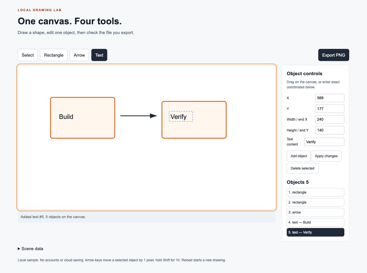
Build a drawing app you can check in five steps: create rectangles, connect them with an arrow, add editable labels, move one object and export a PNG. Start with the working example below so you can spend your time understanding and testing the behavior instead of assembling a toolbar from scratch.
We ran this app ourselves. Thirteen model checks passed, and a separate browser pass covered drawing in opposite directions, text editing, selection, movement and deletion. The exported image reopened at 960 × 540 pixels, with zero changed color channels compared with the canvas used to encode it.
Open the drawing lab or download the app, tests and retained results. Every step screenshot below is a raw capture of that working example, with separate arrows and short focus labels to guide your eye. The cover is also an original capture; no interface text or test result has been replaced inside an image.
Follow the workflow
- 1. Open the working app and set the scope
- 2. Create rectangles in both directions
- 3. Connect the shapes and edit their labels
- 4. Select, move and delete one object
- 5. Export the drawing and check the PNG
Before you begin
The hosted lab runs in a browser. To work locally, unzip the download and open a terminal in its root folder. You need Node to run the model checks and Python 3 to serve the files; the drawing app itself has no package-install step.
REA is needed only for the analysis section, not for drawing or exporting. If you have not connected it yet, follow the REA setup guide.
This is an original learning app with a small, inspectable implementation. It is useful for practicing the connection between code evidence and observed behavior. It does not demonstrate recovering a commercial product or generating a complete app from an unavailable source.
1. Open the working app and set the scope
From the extracted kit root, run the tests first:
node tools/drawing-app/test.mjsThe command writes tools/drawing-app/evidence/model-tests.json and exits unsuccessfully if an assertion fails. Our retained result contains 13 passing checks out of 13. Those are model checks; the browser interactions in the following steps are a separate pass.
Now start the local server:
python3 -m http.server 4422 --bind 127.0.0.1 --directory publicOpen http://127.0.0.1:4422/labs/drawing-app/. You should see a blank canvas, four tool buttons and an Object controls panel. If port 4422 is already occupied, choose another port and use the matching address.
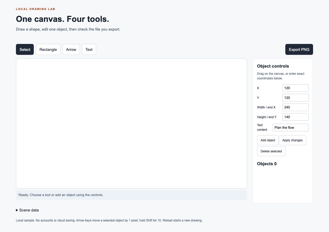
Focus: the four tool buttons and the empty Objects list. Start with an empty scene so you can tell exactly which action creates each object.
The example separates two responsibilities. model.mjs creates and moves shape objects, checks selection and serializes the drawing. app.mjs connects that model to pointer events, the controls and PNG export. If you change the project, preserve that separation: test geometry without needing to open the interface, then test the interface against the same model.
Keep the first version limited to:
- Rectangles and directional arrows.
- Text placement and editing.
- Single-object selection, movement and deletion.
- One PNG export size.
Undo history, grouped objects, collaboration and saving between sessions are outside this version. Reloading starts a new drawing.
2. Create rectangles in both directions
Choose Rectangle. Drag from the upper-left toward the lower-right in the left half of the canvas. Then create another rectangle in the right half, this time starting at the lower-right and dragging toward the upper-left.
Both objects should appear with positive dimensions. The second drag is useful because a model that assumes every drag travels right and down will often produce a negative width or height.
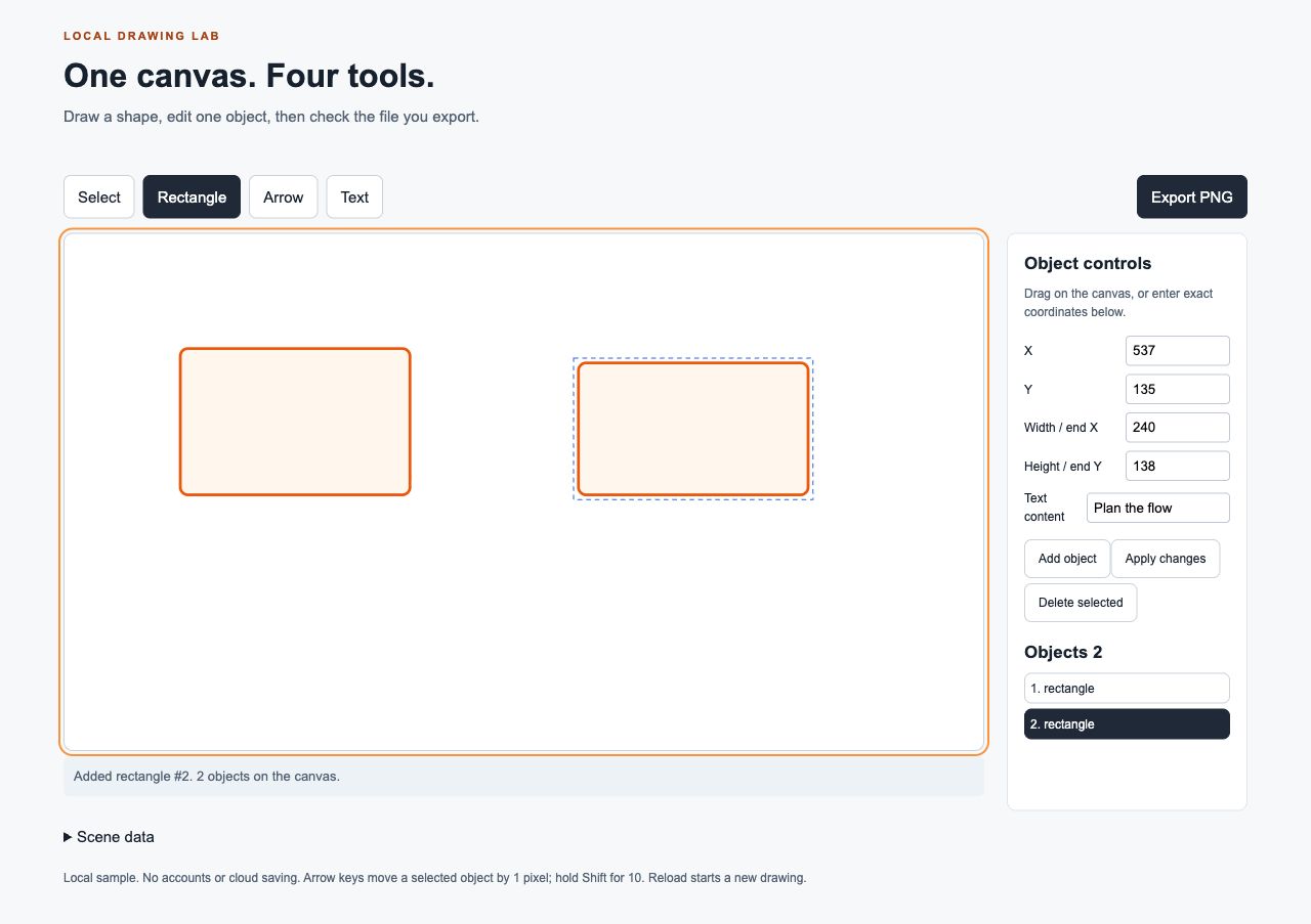
Focus: two visible rectangles and an Objects count of 2. The selected rectangle’s X, Y, width and height appear in the controls.
Our first browser rectangle had dimensions 240 × 153 model pixels; the reverse-drag rectangle was 240 × 138. Your hand-drawn values will differ. The important result is that both dimensions remain positive and both objects can be selected.
The model computes the rectangle’s upper-left corner from the smaller coordinate on each axis, then takes the absolute difference for its size:
const x = Math.min(start.x, end.x);
const y = Math.min(start.y, end.y);
const width = Math.abs(end.x - start.x);
const height = Math.abs(end.y - start.y);
The included model check also rejects a zero-width rectangle. That check does not substitute for dragging in the actual browser; it verifies the geometry rule independently.
For precise placement, choose Rectangle, enter X and Y plus Width and Height, and use Add object. In this panel, width and height describe rectangle dimensions. The same last two fields become endpoint coordinates when you use the Arrow tool.
3. Connect the shapes and edit their labels
Choose Arrow and drag from the first rectangle toward the second. The arrowhead should point toward the release point. If you want a horizontal connector, select the arrow, set Y and Height / end Y to the same value, then click Apply changes.
Choose Text, enter Draft in Text content, and click inside the first rectangle. While that text object is selected, replace the content with Build and click Apply changes. The existing label should change without increasing the object count.
Next, enter Verify and click inside the second rectangle to place a second label.
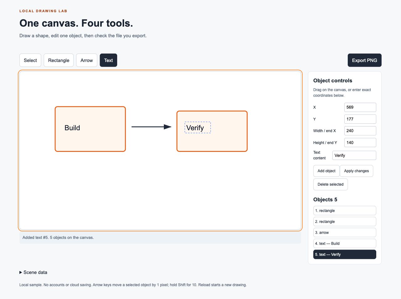
Focus: the edited Build label and five objects in the list. The scene now contains two rectangles, one arrow and two text objects.
We performed that edit in the browser: Draft became Build, and the text retained its object ID. We also drew a separate reverse-direction arrow later in the test and confirmed that its endpoint X was smaller than its starting X before deleting it.
Keep arrow direction separate from rectangle normalization. A rectangle can use the minimum X and Y as its origin. An arrow needs to retain which point was the start and which was the end, otherwise a reverse drag can produce an arrowhead on the wrong side.
Text is stored as literal content and escaped when the drawing becomes SVG. The model test uses characters such as <, > and & to check that they are serialized as text rather than inserted as executable markup.
4. Select, move and delete one object
Choose Select, then click the second rectangle in the Objects list. Focus the canvas and press Shift + Down Arrow once. This should move that rectangle down by ten model pixels.
Now drag from an empty part inside that rectangle to a nearby position. Avoid the text label when you want the rectangle: the example selects the topmost matching object, so clicking the label can select text instead.
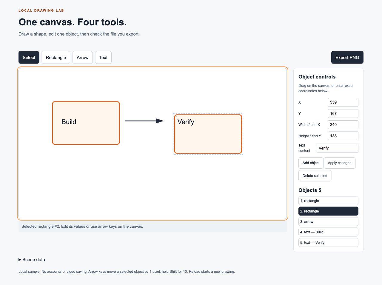
Focus: the blue selection outline and the selected rectangle’s coordinates. The text label and arrow are separate objects; they do not move as a group.
Our browser observations showed:
| Action | Observed result |
|---|---|
| Shift + Down Arrow | Rectangle 2 moved from Y 135 to Y 145 |
| Pointer drag | Rectangle 2 moved from X 537, Y 145 to X 559, Y 167 |
| Compare the other four objects | Their stored coordinates and text were unchanged |
| Add and delete a temporary reverse arrow | The original five objects remained |
Expand Scene data if you want to compare values before and after an action. It shows the current model rather than a separate manually maintained result table.
To check deletion yourself, add a temporary shape, select it and click Delete selected. The count should decrease by one while the other objects remain. For a broader testing method, use the REA findings verification guide.
5. Export the drawing and check the PNG
Click Export PNG. The app creates an SVG from the scene without the blue selection outline, draws it onto a 960 × 540 canvas and encodes a PNG. It then decodes that PNG again and compares its RGBA channels with the encoding canvas.
Scroll to Export check. You should see the reopened drawing, its dimensions, its byte size and the comparison result. Use Download PNG to keep the file.
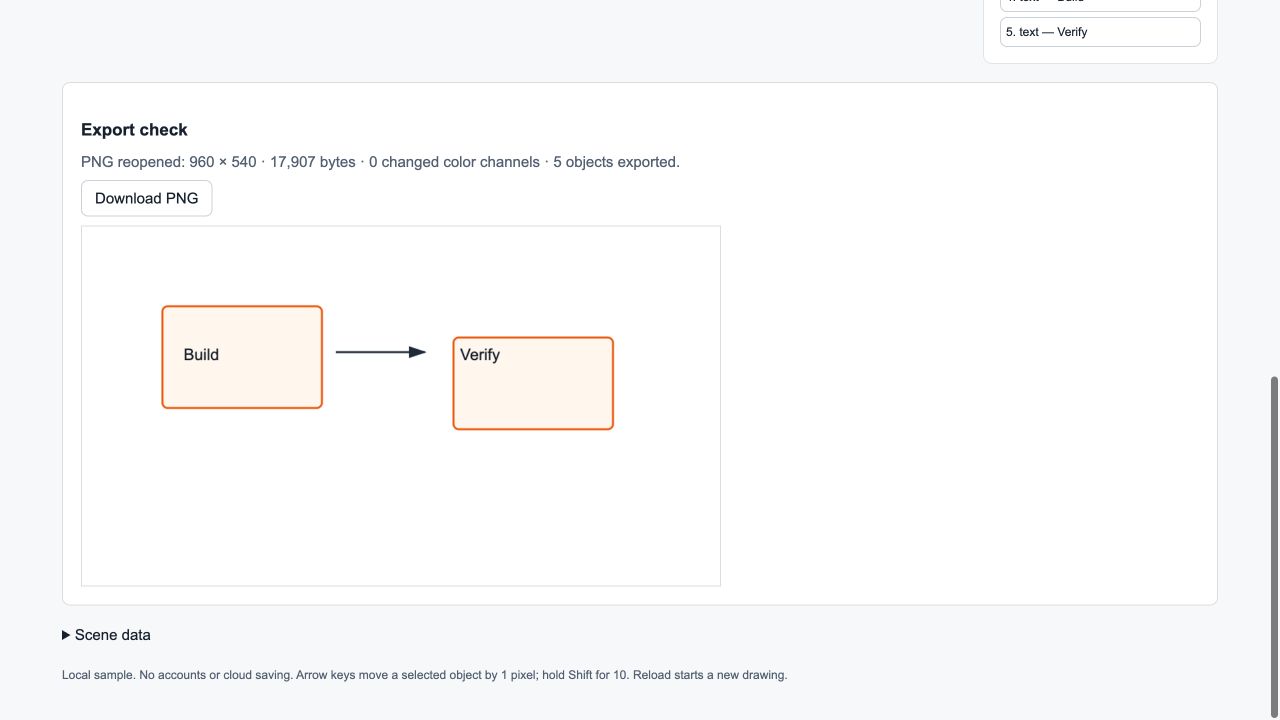
Focus: 960 × 540, 17,907 bytes and 0 changed color channels. Those are the values from our five-object export. Font rendering and a different drawing can change your file size.
The zero-channel difference establishes a narrow result: this PNG decoded back to the same pixel data used to encode it in this browser run. It does not prove that every possible drawing exports correctly or that different browsers render text identically. We also downloaded the actual file; it is included as tools/drawing-app/evidence/drawing.png.
Before you call your own version complete, check that:
- The exported image includes all intended objects.
- The selection outline is absent.
- The file opens at the expected dimensions.
- Text is readable and arrowheads point in the intended direction.
- Changes you make to the app still pass the model checks and the browser workflow.
Where REA fits into this exercise
Once the small app is working, use REA to inspect its delivered JavaScript and compare the static evidence with what you just observed. This keeps the investigation attached to a specific question instead of a request to explain every feature at once.
With the REA CLI already installed, run this from the extracted kit root:
rea analyze-javascript-application "$PWD/public/labs/drawing-app" \
  --detail summary \
  --evidence_output "$PWD/rea-evidence-new.json" \
  --format json > rea-summary-new.json
We ran the analysis on the same app used in the screenshots. REA parsed two JavaScript files, with zero parse failures, and returned 14 findings. Its summary also reported 485 semantic graph unknowns. Those are analysis-coverage limits, not a count of broken drawing features.
REA parsed these files as inert text. It did not draw the rectangles, press the keys or verify the PNG. The browser pass supplied that separate runtime evidence. The download retains the complete REA result, the compact summary, the model-test report and the browser observations so you can inspect their boundaries yourself.
For an agent-assisted follow-up, keep the question specific:
Inspect this local drawing app with REA.
Explain how moving the selected rectangle preserves other objects.
Give exact code/evidence references and separate static findings
from runtime claims. Compare the explanation with the supplied
before-and-after scene snapshots. List anything not established.
Do not add features or report tests that you have not run.
That is a suggested prompt, not a claimed completed model response. The scoped prompt guide helps turn the answer into a small implementation brief. If your next change involves screenshots and annotations, continue with the tested annotation handoff.